This is only Software for WX LCD board with added function of decoding basic GPS NMEA sentences $GPRMC and $GPGGA. Next added feature is to measure temperature using SMT 160-30 sensor. If SMT is used, it has to be connected to X2-1(+5V), X2-2 (OUT), X3-2 (GND).
After succesfull initialization LED flashes 3 times. (One short flash and 2 longer flashes.) If LED is steady in ON state there is a problem with comunication between porcessor and LCD module. After 3 flashes a firmware version is displayed on LCD and also send on RS-232 port. If SMT sensor is found the measured temperature is displayed too. If You do not use SMT sensor, pin X2-2 should by connected to ground. This state means there is no sensor connected and during receive of valid GPS/NMEA data temperature is not measured - it increases program speed. In case that GPS/NMEA data are invalid program tests if SMT sensor is connected and if SMT is found it starts to measure temperature. Temperature measurement is processed just after decoding of received GPS/NMEA data. Because of timing it is divided into 4 parts, so the whole temperature is measured (and refreshed on LCD) in 4 second cycles). You can switch program to only temperature measurement mode by connecting pin X3-1 to ground. In this mode the temperature is measured in 400ms interval, but no GPS/NMEA data are decoded. During program run LED indicates successful receive of $GPRMC and $GPGGA sentences by flashing. In case of valid GPS/NMEA data there is short flash. In case of invalid data there is long flash. LED flashes in temperature mode too (shortly after every measurement).
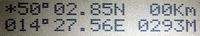
First screen displayes coordinates in hundrets of minutes, speed and level above the see.
Second screen displayes time (UTC), date (day,month - 7.aug. on the picture), number of tracked satelites (5 on the picture), speed, direction, and if SMT is connected it's temperature. If SMT is not connected, validation marks from $GPRMC and $GPGGA are displayed(A1 on the picture).
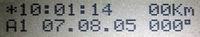
* in up-left corner means valid GPS fix, ! means invalid.
Program accepts following comands from RS-232 inteface:
^V sends software version text
^U sends EEPROM contents
^D writes follwing bytes to EEPROM (but there has to be min 80miliseconds delay between bytes)
^M measures tepmerature from SMT sensor
^R sends processor's registers contents (for debugging)
^r sends WX registers contents (for debugging)
characcter ^ means ESC key - all commands are composed as two keys commands first is ESC and next is one letter from above table
For download EEPROM contents and upload back into processor's EEPROM use of Piceerw program is recomended. full installation 1.4MB; exe only, needs ocx libraries (36kB)).