Control functions:
Control Function trimr R1 contrast LCD Switch S1 backlight LCD Button S2 multifunctional Button S3 multifunctional Pin X2-1 +5V Pin X2-2 SMT-160 Pin X3-1 AUDIO from TRX Pin X3-2 GND
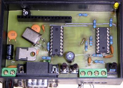
Eagle 4.03 (displayed bitmap may not give the accurate dimensions 85x54mm)
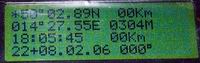
Example of GPS tracking with SMT on LCD 4x20chars:
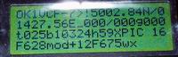
And AX.25 frame decoding:
Part      Value

C1       15p
C2       15p
C3       100n
C4       100n
C5       100n
C6       100n
C7       33u
C8       100n
C9       47n
C10      39p
D1       LED3MM
IC1      PIC16F628/xxP
IC2      7805
IC3      MX614
JP1-JP4  Jumper female 16pin
Q1       3.579MHz
R1       25K trimr
R2       1K0
R3       10K
R4       330
R5       10K
R6       10K
R7       10K
R8       10K
R9       100K
R10      100K
R11      10K
R12      100K
S1	 switch P121
S2       button
S3       button
X1       W237-02P (screw connector 2pin/5mm)
X2       W237-02P (screw connector 2pin/5mm)
X3       W237-02P (screw connector 2pin/5mm)
X4       M09H (Canon 9 male to the PCB)
LCD	 LCD (witch backlight) 2x16 chars HD77480 controller compatible
Otherwise Power source could be from 7 to 30V.
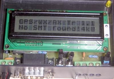
GPS-SMT-AX-WX-LCD module is designed for displaying data from PIC WX full weather station or NMEA data from GPS receiver or tepmperature from directly connected sensor SMT-160 or AX.25 frames. Connection between this module and weather station (or GPS receiver) is made by direct RS-232 cable or simply by connection of the pins 5 and 2 of this module and weather station (or GPS receiver).
Every time when data from weather station are received LED flashes shortly. After powering up LED flashes once which idicates succesfull inicialization. If LED is steady in ON state there is probably a problem with comunication between processor and LCD module.
In GPS+SMT mode (default mode) this module displays data from GPS receiver and SMT (if connected) in the same manner as GPS / SMT LCD module.
In WX mode this module displays data from weather station - in the same manner and button functions as WX LCD module.
Module itself switches between GPS+SMT and WX by the received data on RS-232 input. Or You can switch modes by S2, S3 buttons manually.
In AX.25 decoder mode part of the decoded AX.25 frame is displayed on the LCD (Source call, Info field). To RS-232 out the complete first 190 bytes of AX.25 frame is sent.
You can choose speed of RS-232 communication for all modes (it is done by buttons S2, S3)
If You do not plan to use AX.25 decoder function You can omit FX-614 and resistors + condensators which FX-614 needs for functionality.
It is also possible to burn this software into PIC 16F628 in the circuit for WX LCD. In this case You have to change crystal 4MHz to 3.579MHz or assemble software with constans for 4MHz crystal. (they are commented in source code). I recommend to add 100K resistor into mentionned circuit WX LCD from pin 1 a GND (for better SMT sensor detection). All function of this software except AX.25 decoder are available when using former circuit (mentionned above).
Version 2.0 supports both LCD 2x16 and LCD 4x20. LCD type is stored in EEPROM on the address 07h. Char '4' = 4x20, char '2' = 2x16.
After successfull initialization LED flashes 3 times. (One short flash and two longer flashes). If LED is in steady ON state there is a problem with LCD communication. If S2 or/and S3 is/are pressed before last flash of the LED it invoke manual mode switching:
- Button S3 (LCD): mode SMT tepmerature measurement only. To exit this mode press button S3 (for entering GPS+SMT / WX mode) or S2 (for entering AX.25 decoder mode)
- Button S2 (AX25): communication speed is set to 4k8 and GPS+SMT mode is entered
- Both buttons: communication speed is set (from default 4k8) to 9k6 - it is needed for communication with mentioned weather station or for configuration software described below - it uses 9k6 speed
Program accepts following comands from RS-232 inteface:
^V sends software version text
^U sends EEPROM contents
^D writes follwing bytes to EEPROM (but there has to be min 80miliseconds delay between bytes)
^M measures temperature from SMT sensor
^R sends processor's registers contents (for debugging)
^r sends GPS/NMEA registers contents (for debugging)
^W sends WX registers contents (for debugging)
^w following bytes are considered as output from PIC WX full weather station and are decoded and displayed on the LCD
Character ^ means ESC key - all commands are composed as two keys commands first is ESC and next is one letter from above table
For download EEPROM contents and upload back into processor's EEPROM use of Piceerw program is recomended. full installation 1.4MB; exe only, needs ocx libraries (36kB)).